
The Space Race
Puzzle 13 · Rockets and Launch Pads · Page 27 in print
The F-1 Engine
The F-1 began in 1955 as an Air Force order to Rocketdyne for a million pounds of thrust.
Jump to a word
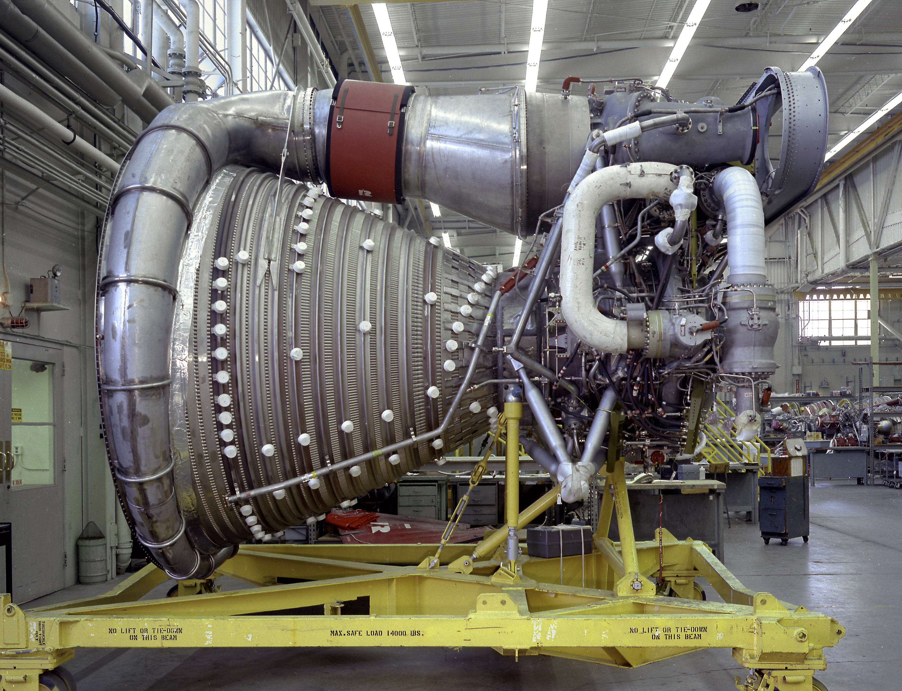
An F-1 engine assembly on a support stand, with its large nozzle at left.
NASA / Marshall Space Flight Center (6862832) · NASA media-use guidelines · Original recordThe words
Baffles
Copper baffles divided the F-1 injector face into compartments. They helped suppress combustion instability, a problem that could destroy an engine.
Bomb Test
Engineers used explosive disturbances during F-1 ground tests to see whether combustion returned to stable operation. These tests evaluated the baffled injector’s response to instability.
Canoga Park
Rocketdyne researched, developed and manufactured the F-1 at Canoga Park, California. Other sites handled component and full-engine tests.
pp. 106–107 · Bilstein: F-1 development and components (opens a new tab)
Edwards
Edwards Air Force Base was the center for full-scale F-1 testing. A prototype thrust chamber was tested there on April 6, 1961.
pp. 106–107 · Bilstein: F-1 development and components (opens a new tab)
Gas Generator
The F-1 gas generator burned kerosene and liquid oxygen to power the turbopump. This smaller combustion system supplied energy for the engine’s propellant pumps.
Did you know?
In January 2013, NASA tested an F-1 gas generator at Marshall to gather new performance data for studies of future heavy-lift propulsion.
Gimbal
A pivoted mounting that permits swiveling.
Four outer F-1 engines could swivel to steer Saturn V. The fifth engine, at the center of the first stage, stayed fixed.
Heat Exchanger
The F-1’s heat exchanger warmed oxygen and helium for the first stage’s tank-pressurization system. Those gases helped maintain pressure in the propellant tanks.
p. 122 · Bilstein: F-1 development and components (opens a new tab)
Inconel
Rocketdyne chose the nickel alloy Inconel X-750 for F-1 thrust-chamber tubes. Its strength relative to its weight suited the large engine.
Bilstein: F-1 development and components (opens a new tab) · Smithsonian: F-1 engine and materials (opens a new tab)
Injector
The F-1 injector fed liquid oxygen and fuel into the combustion chamber. Its design became central to the effort to control destructive combustion instability.
Instability
Combustion instability caused pressure swings and violent vibrations in the F-1. The resulting damage could destroy an engine, making this a major development problem.
Nozzle
The F-1’s bell-shaped nozzle had an extension that increased exhaust expansion. Turbine exhaust formed a cooler layer protecting the extension’s walls.
pp. 109, 121–122 · Bilstein: F-1 development and components (opens a new tab)
Rocketdyne
Rocketdyne began F-1 development under an Air Force contract in 1955. NASA continued the work with a contract in January 1959, before the engine powered Saturn V’s first stage.
Did you know?
For its 2022 Destination Moon exhibition, the Smithsonian arranged one whole F-1 and a quarter-section with mirrors to suggest a cluster of five engines.
Santa Susana
Santa Susana Field Laboratory hosted F-1 component testing. Testing parts separately helped Rocketdyne develop the engine without using a complete engine for every early trial.
pp. 106–107 · Bilstein: F-1 development and components (opens a new tab)
Thrust Chamber
Fuel circulated through tubes in the F-1 thrust chamber’s walls before combustion. This carried away heat while the chamber contained the burning propellants.
pp. 109, 119–120 · Bilstein: F-1 development and components (opens a new tab)
Turbopump
The F-1 turbopump delivered the engine’s kerosene fuel and liquid oxygen. Its two propellants served different roles: fuel to burn and oxygen to support combustion.
Did you know?
The Smithsonian’s cataloged F-1 was built in 1963 and underwent four start tests totaling 192.6 seconds before entering the museum collection.
Sources
- F-1 Rocket EngineNational Air and Space Museum
- A New View of the Rocketdyne F-1 EngineColleen E. Anderson; National Air and Space Museum, November 2, 2022
- Stages to Saturn: A Technological History of the Apollo/Saturn Launch VehiclesRoger E. Bilstein; NASA History Series, NASA SP-4206, 1980; printed pp. 106–109 and 119–123
- Solving Combustion Instability and Saving America’s First Trips to the MoonJennifer A. Harbaugh; NASA, July 12, 2019
- World’s Most Powerful Engine Blazes Path for Space Launch System Advanced PropulsionBeth Ridgeway; NASA, January 24, 2013